Learning by doing is in most of the time the best practice approach in IT. Even the best training slides won’t deliver the same experience when using an environment you are interested to get used to.
But – for ACI – this will require quite a lot of stuff – and a basic environment is quite expensive just for learning. That’s why Cisco is offering for certain parties a simulator environment.
Cisco is offering quite a lot of sandbox environments, too.
https://developer.cisco.com/docs/sandbox/#%21data-center/overview
Part of this is the ACI (Ver. 4.0) available via this link.
username: admin
password: ciscopsdt
There is a download available to build up your own lab system.
This consists of a spine, two leafs and an APIC, all in a single VM (identical setup to that one from sandboxapicde).
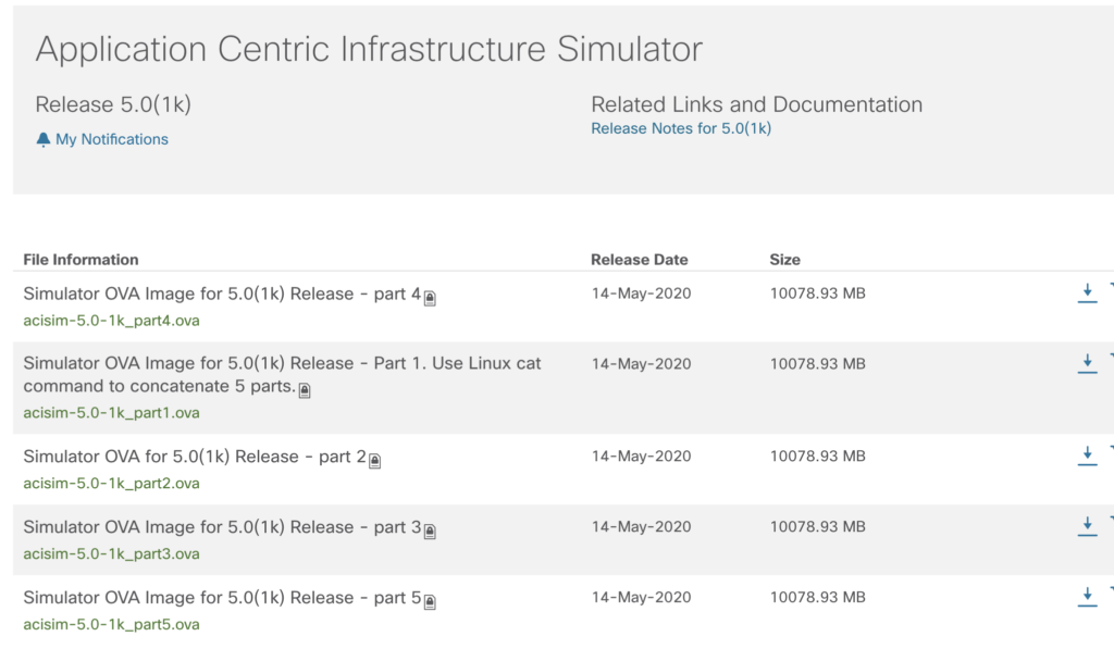
Software (you do need an account with the proper provisioning) can be downloaded at
At the time of this writing the latest version is 5.0 – consisting of five parts, each part is about 10 GB.
Please check as well the release notes for further details:
and as well
First step after downloading – put the five parts together into one file.
On the linux/unix console it is:
cat part1 part2 part3 part4 part5 > aci.ovaand similar in Windows within the command window.
type part1 part2 part3 part4 part5 > aci.ovaJust replace part1 etc. with the names of the downloaded ova parts. The order has to be kept.
To run this ova file, it is possible to use all hypervisors being able to use OVA file format like VMware Workstation or VMware ESXi.
This tutorial is about deploying the simulator on ESXi. This will require some extra steps, as the traditional approach (uploading of the ova file via the webinterface) won’t work due to the size of the ova file (50 GB).
But – this is not a problem. A closer look shows the nature of an .ova file. It is just a tar archive with the ending .ova.
# tar tvf aci.ova

-rw-r--r-- someone/64     5600 2020-05-15 03:03 acisim-5.0-1k.ovf

-rw-r--r-- someone/64      211 2020-05-15 03:03 acisim-5.0-1k.mf

-rw-r--r-- someone/64 4019572736 2020-05-15 03:03 acisim-5.0-1k-file1.bin

-rw-r--r-- someone/64 48823041536 2020-05-15 03:51 acisim-5.0-1k-disk1.vmdk
This technote describes how to deploy an .ova file on ESXi.
Sizing of the VM is crucial – please calculate at least 16 GB or better 24 GB RAM.
As said – it is possible to use VMware Workstation on a PC as well, but RAM requirements are the same.
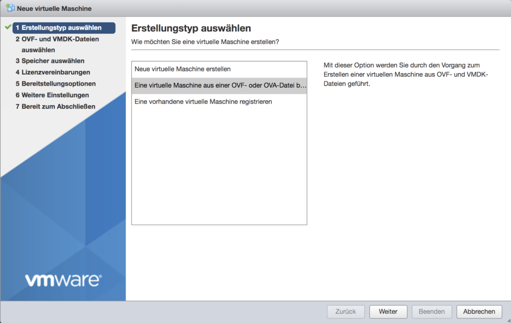
In your Vsphere webclient right-click on your host inventory and select „Create/register VM“ (my screenshots are in german, but quite easy to find the same in your local language).
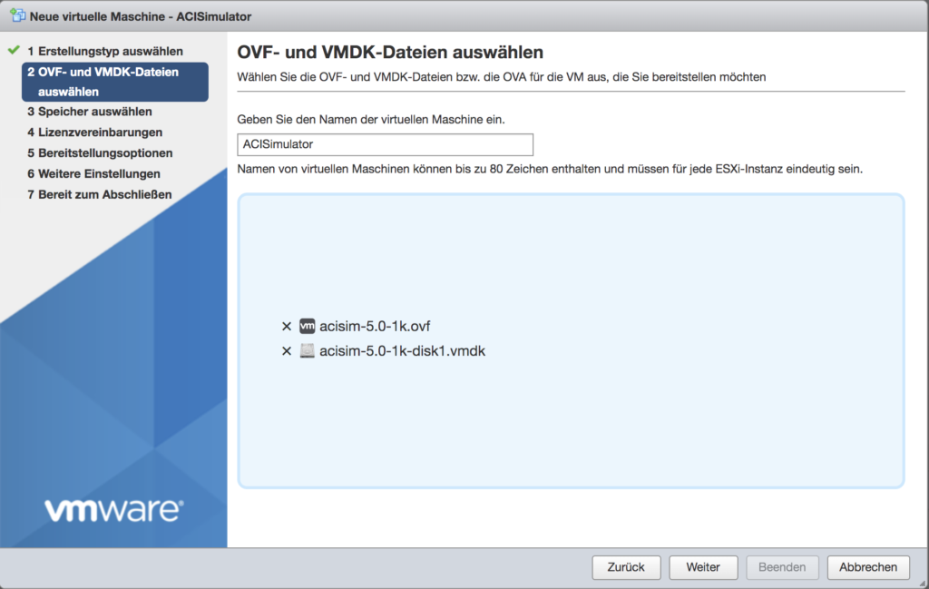
Now choose a name – and – as already mentioned – for smaller OVA files you’d be able to drag-and-drop, but this is limited to 1 GB.
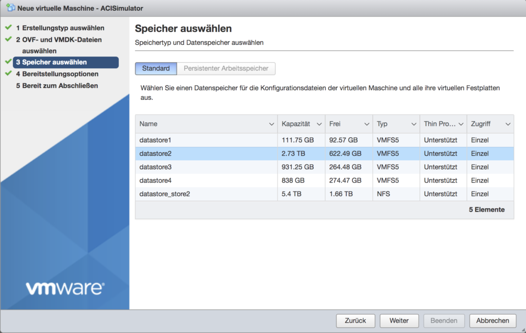
Now select a datastore where the upload will be placed
and a network.
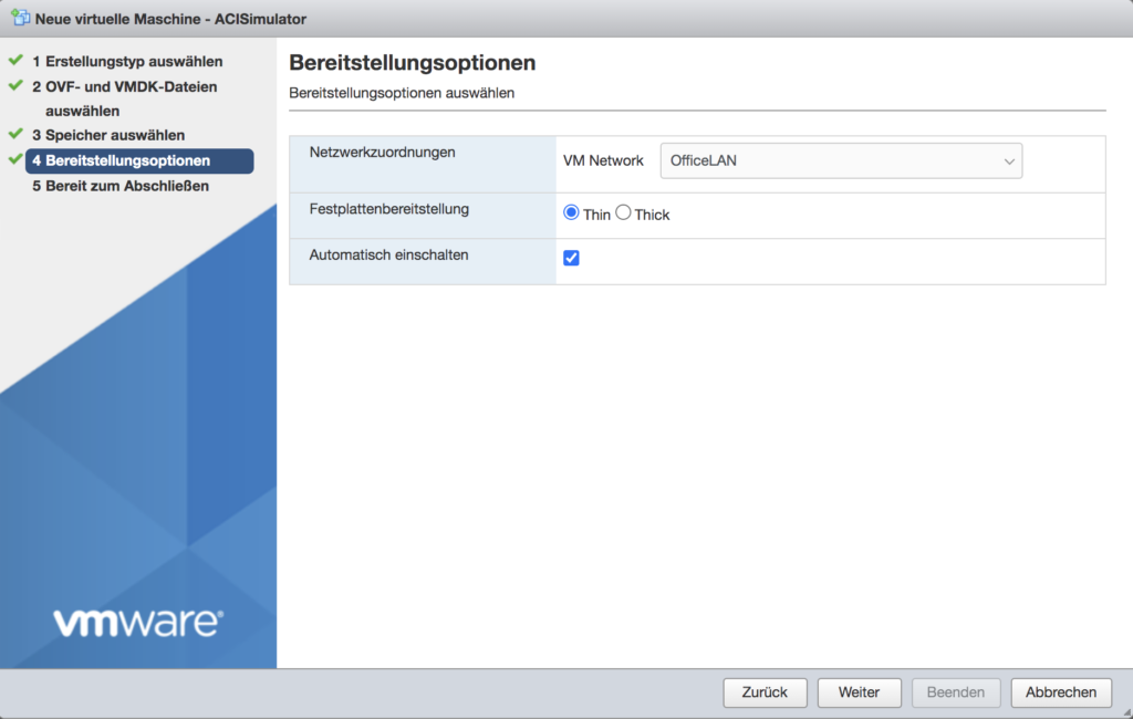
That’s it. Now a little more patience is required – the upload of the disk container will take some time.

After the successful upload you’ll be able to boot the VM.
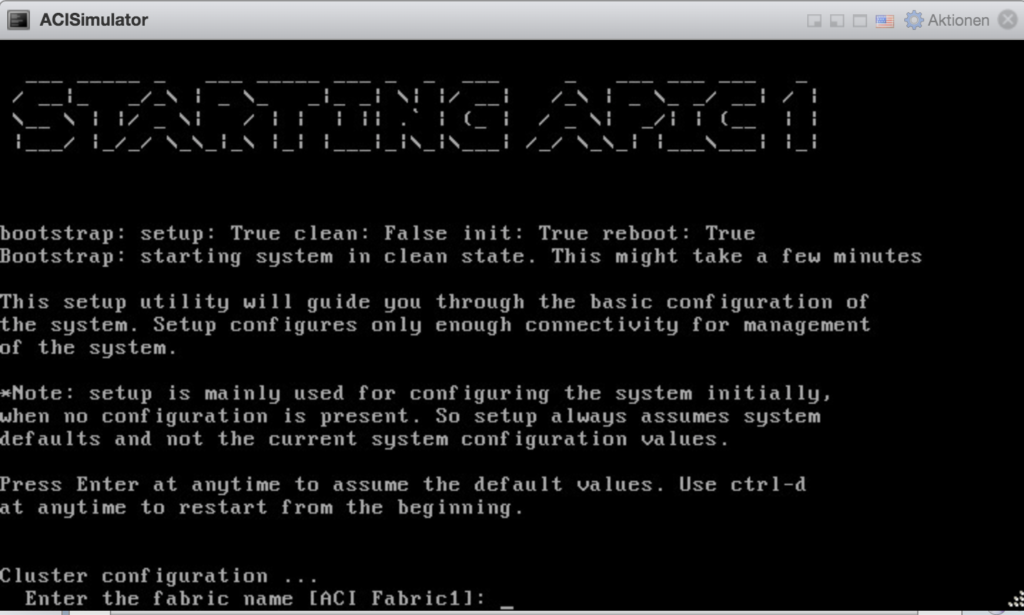
IMPORTANT : The simulator has to be reconfigured after each boot – the configuration isn’t persistent.
Ok – we’ll just use the default values except for the local network details (in this case 192.168.140.40/24).
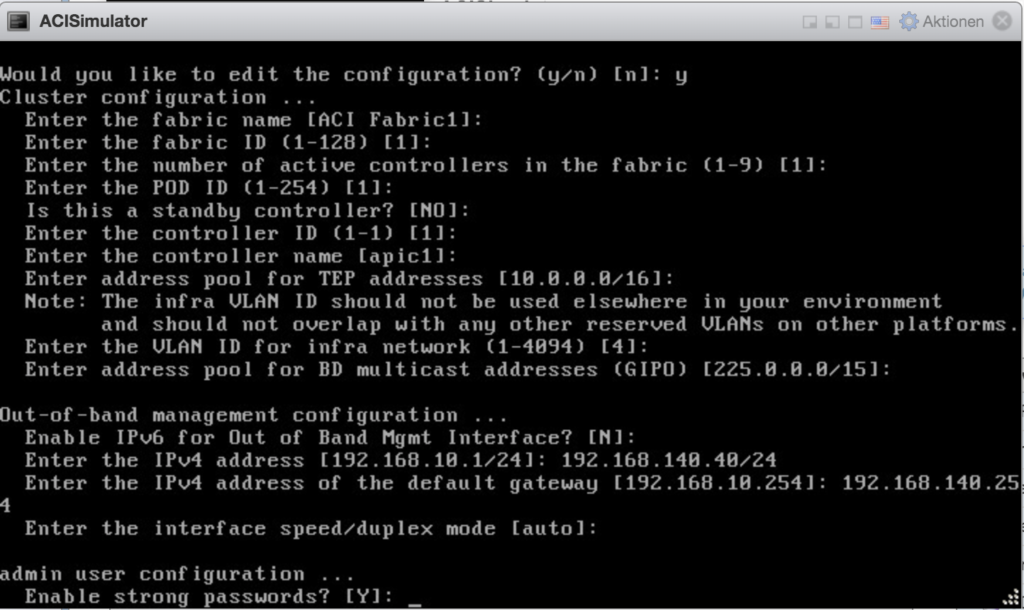
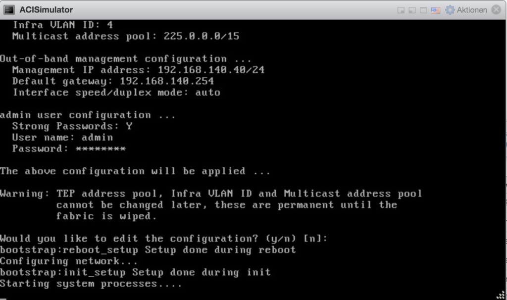
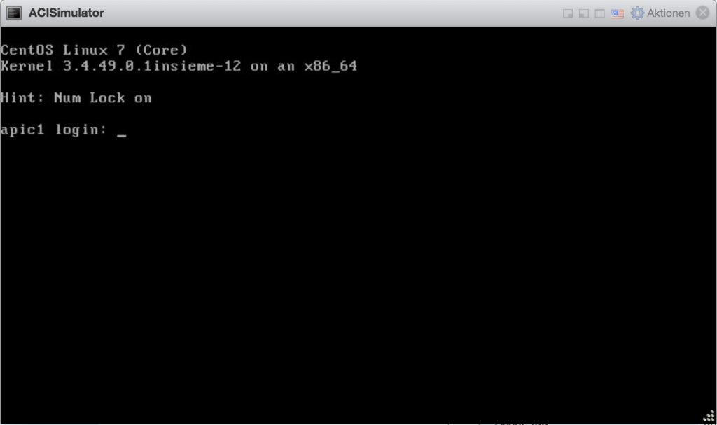
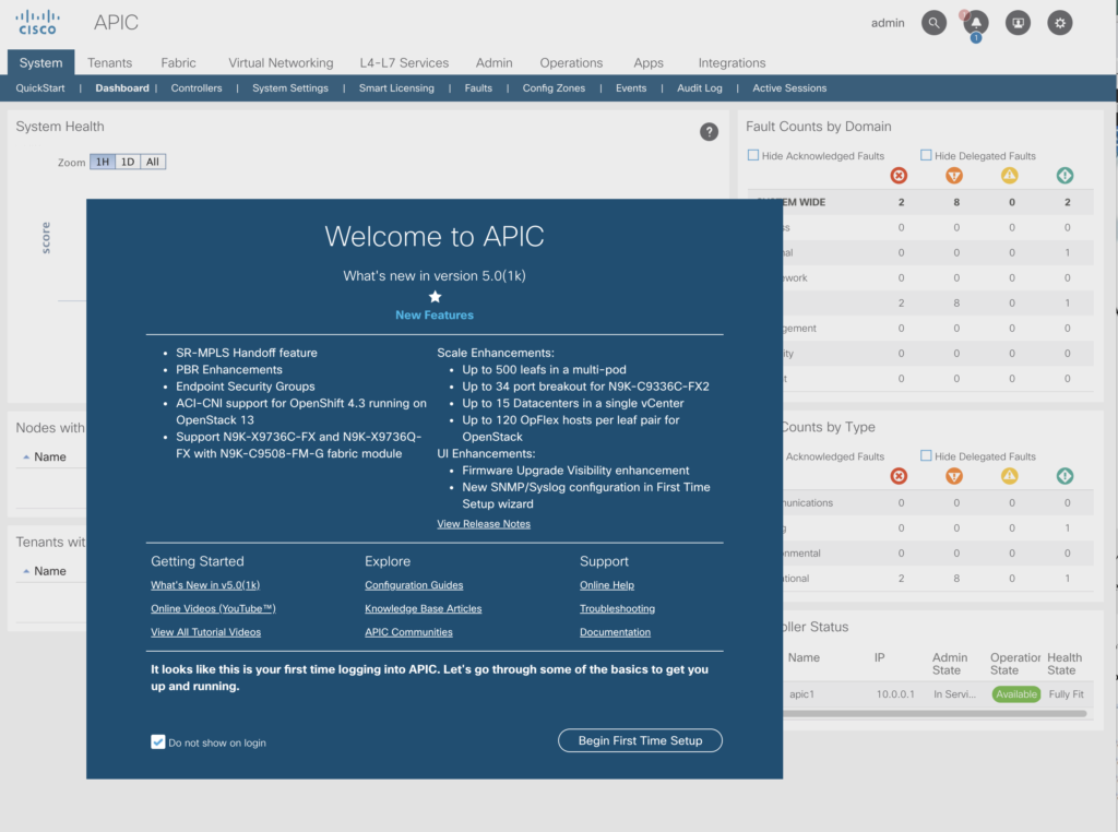
Using the account „admin“ and the password you’ve provided you’ll be able to login.
To get access from the outside world you’ve to set
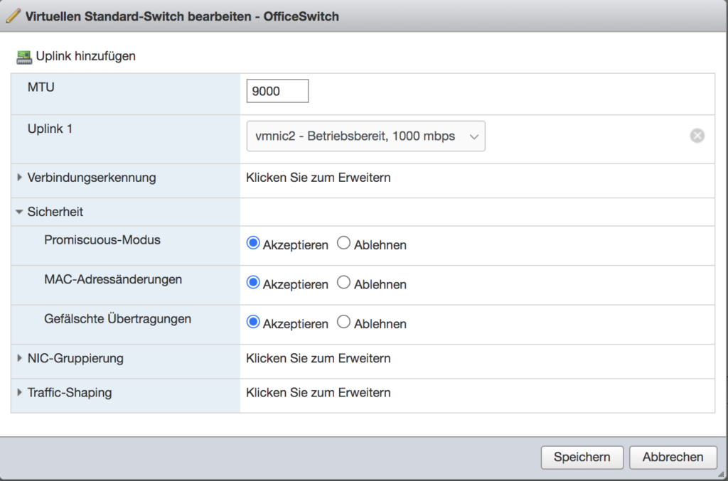
for the virtual switches promiscuous-mode to accept, as well as for mac address changes and forged transits.
After those changes you’ll be able to logon from the „outside“ world.
Lets begin now with the base configuration.
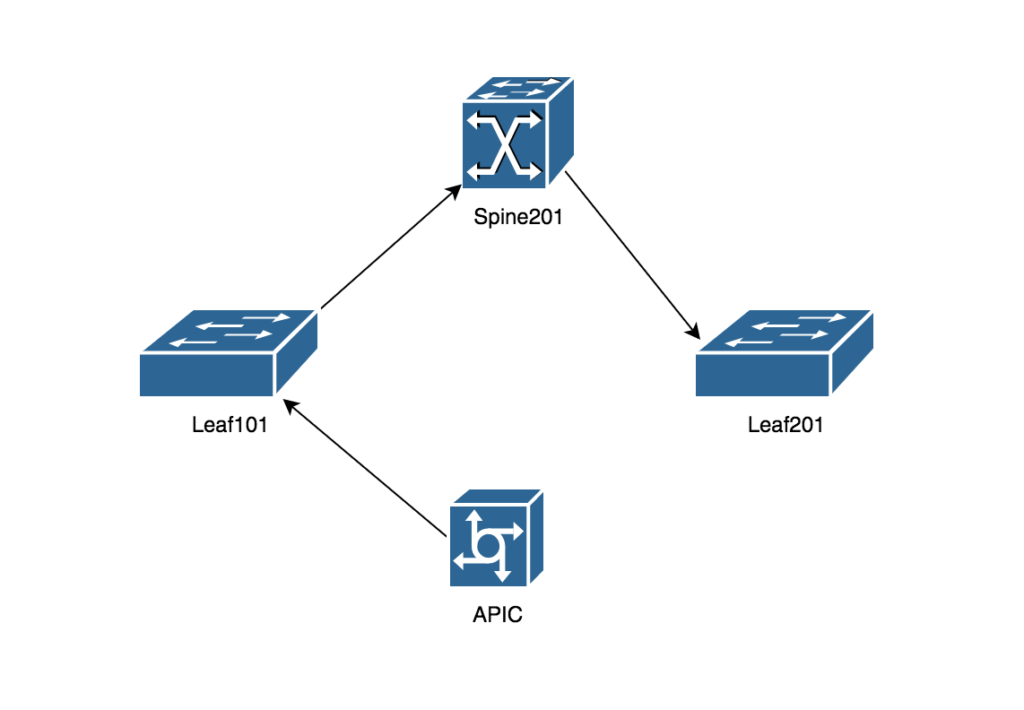
The simulator delivers four entities in one „pod“:
- The APIC
- Two Leaf Switches (N9K-C9396PX)
- One Spine Switch (N9K-C9508)
Lets go now through the basics of a fully working APIC setup.
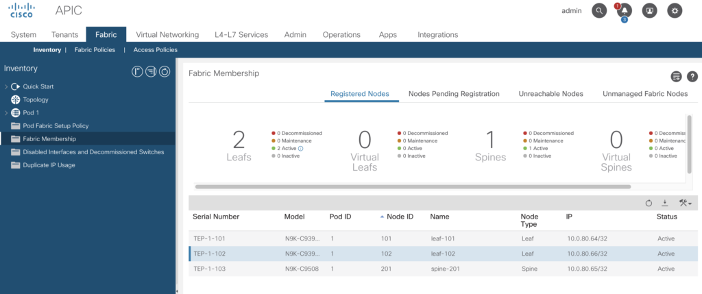
Fabric Membership
Login to your web-based console and click on „Fabric“ -> Inventory -> Fabric-Membership (within the left-pane)
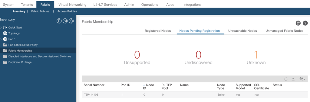
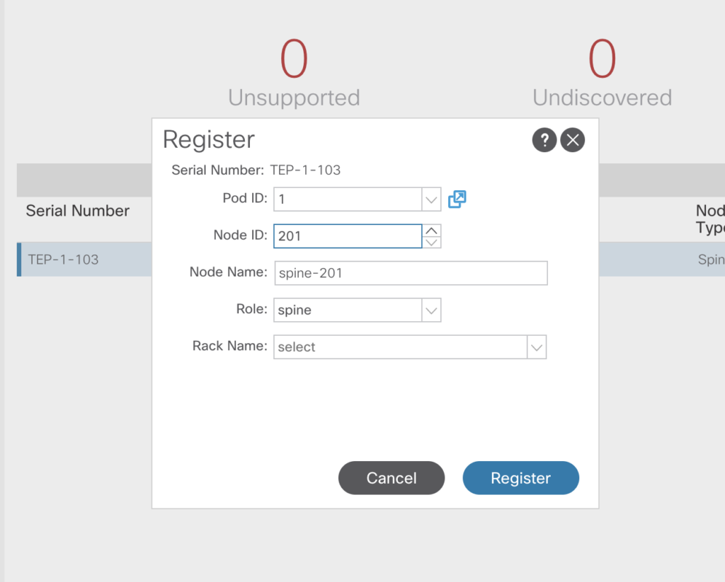
You’ll see there the first leaf – With serial number TEP-1-101. Right click on this one, and select register.
Chose a name and just wait a while.
After some time the spine node will be discovered.
It will be added as well that way.
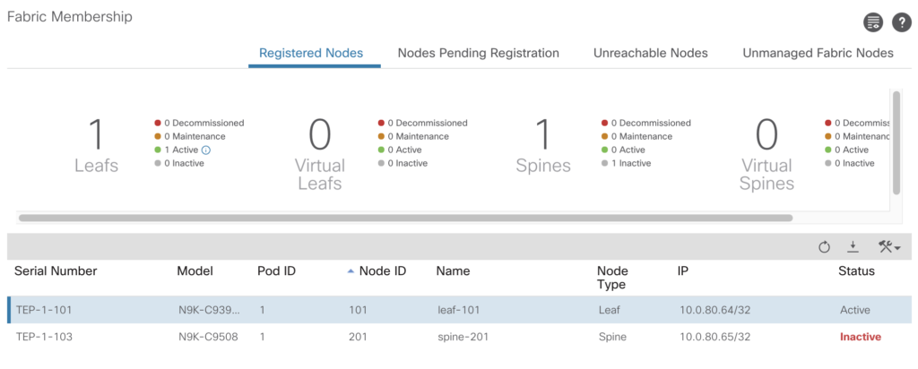
After adding all three nodes, the status should be active.
If you go now to
Fabric -> Inventory -> Topology -> Pane „Topology“ you’ll see your lab setup.
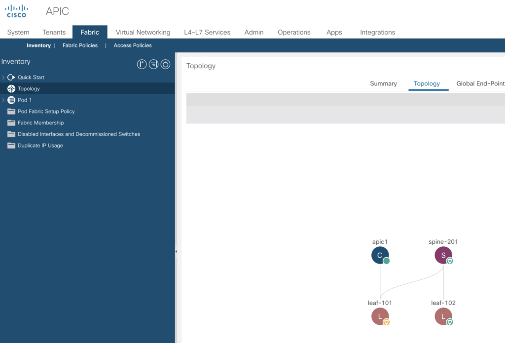
And it will explain the discovery path.
- APIC sees leaf-101 – and adds to inventory
- Now APIC will discover spine-201 – add to inventory
- If spine-201 is active – leaf-102 will be discovered
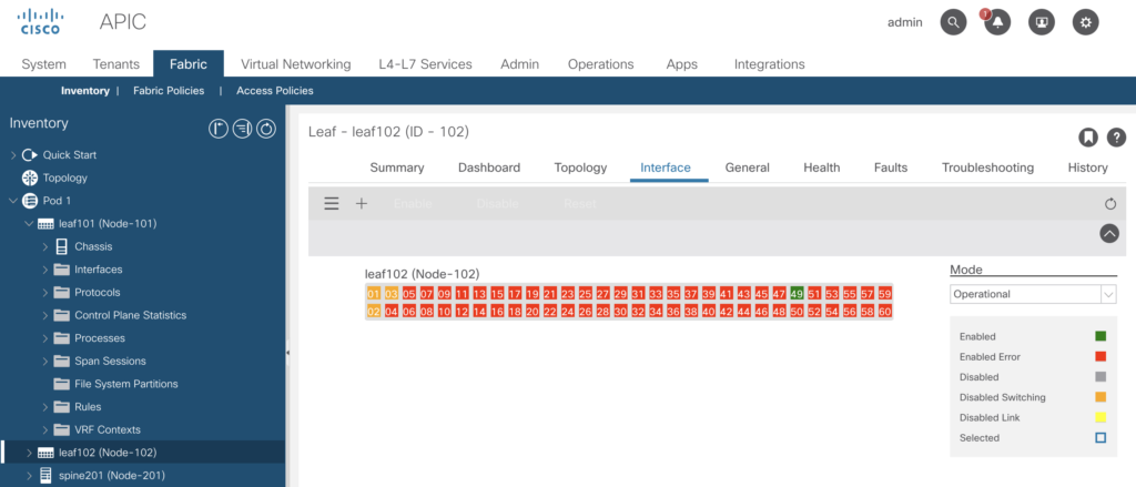
The Fabric -> Inventory -> Pod 1 -> leaf101 -> Sub Tab Interface will display the „physical“ connections to this leaf switch (port 41 and 49 in green).
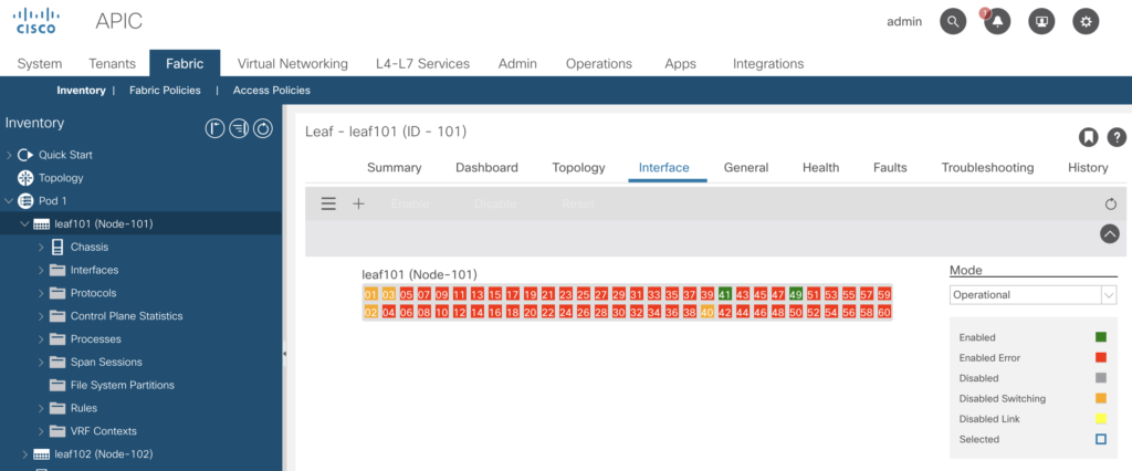
Same for leaf-102 (port 49)
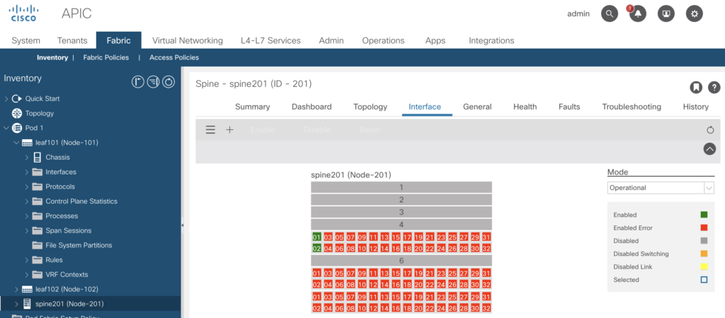
and the spine201 (port 01 and 02).
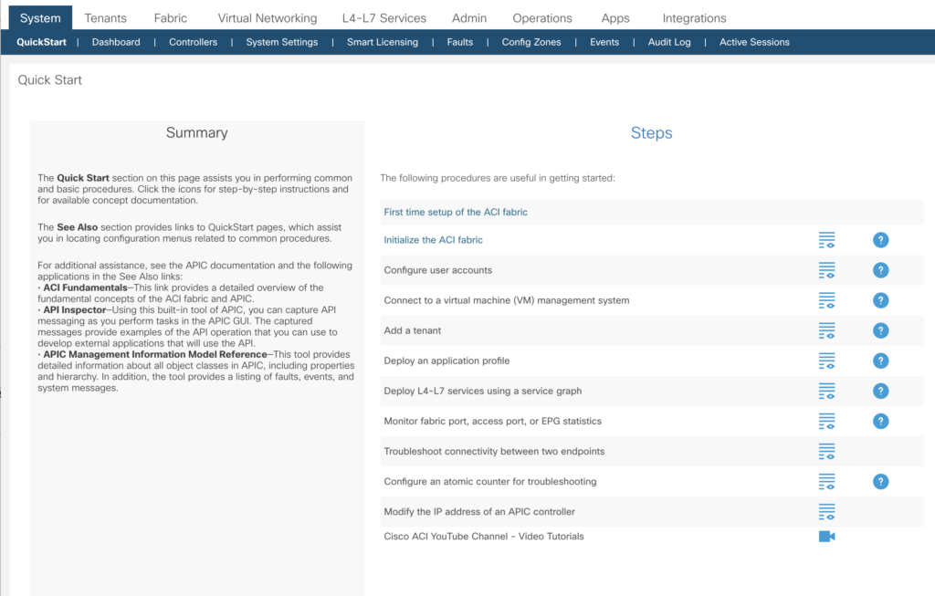
Maybe best to go through the quick start guide first.
Next step
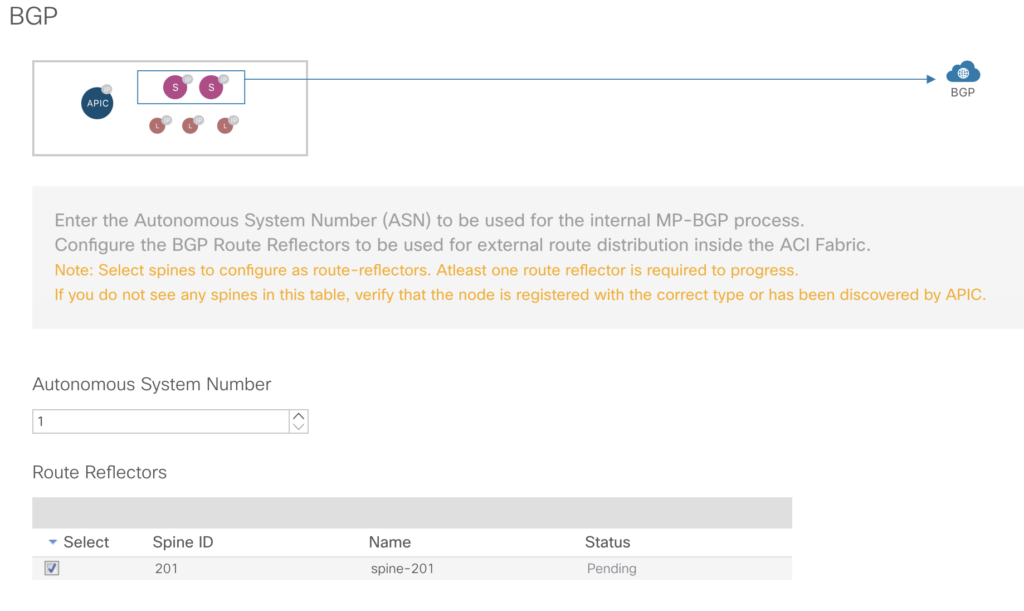
BGP
Out Of Band Management
This takes care of the connectivity to the outside world. The GUI auto-assigns IP-addresses you’ve entered in the field „IPv4 Starting Address“ to the nodes of your simulator setup.
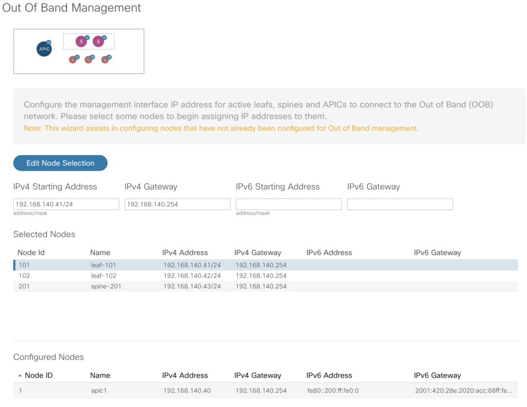
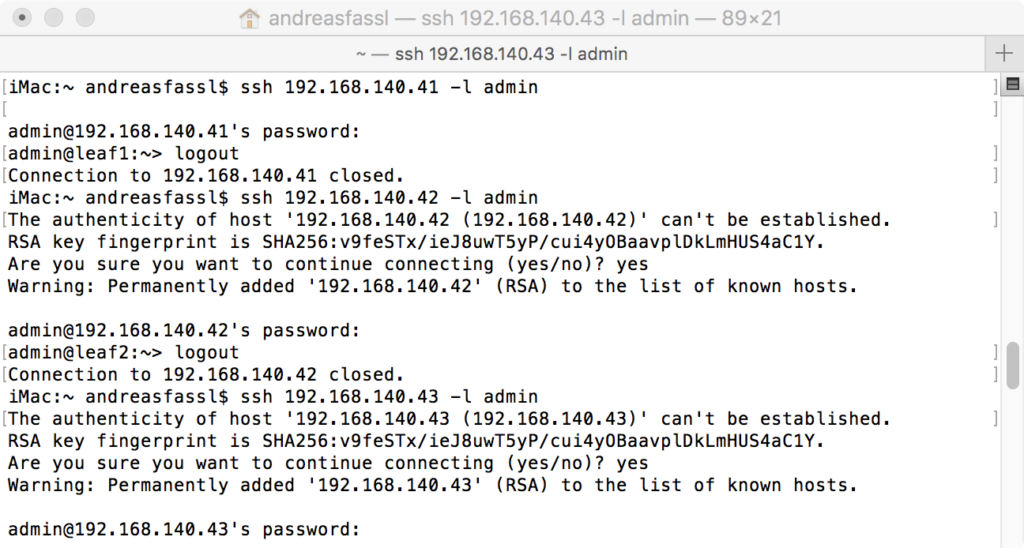
After setting those IP-addresses – you’ll be able to login from your remote system to the components.
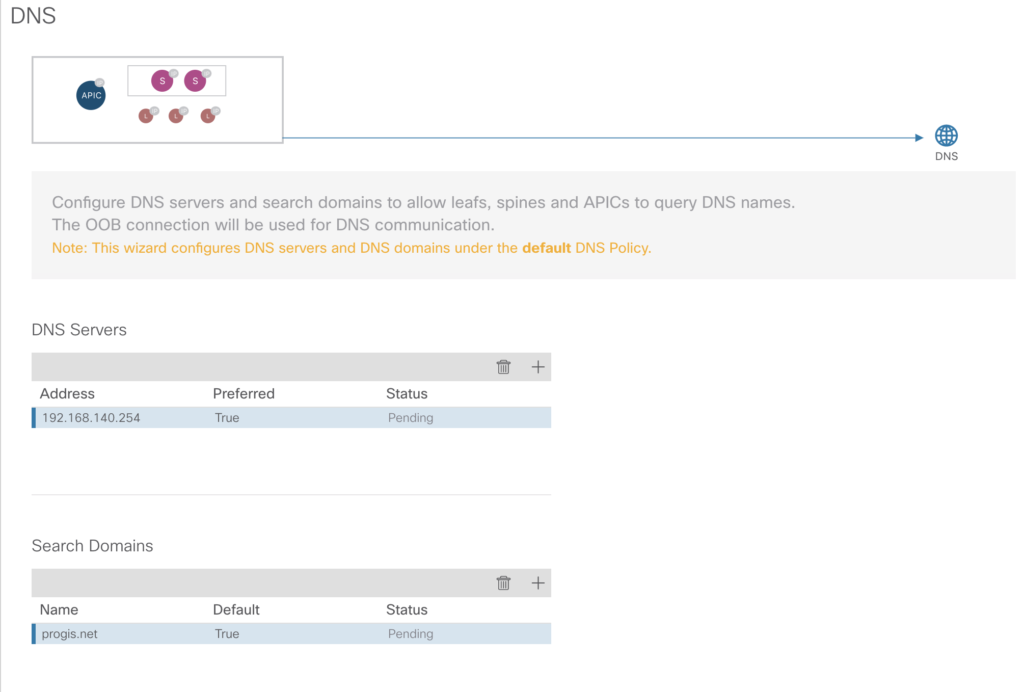
DNS
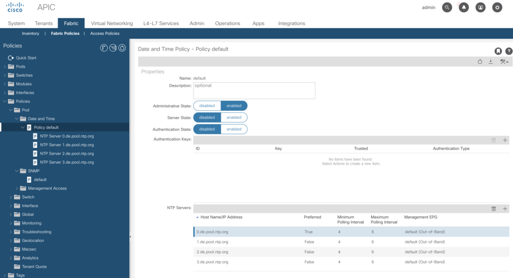
NTP-Servers
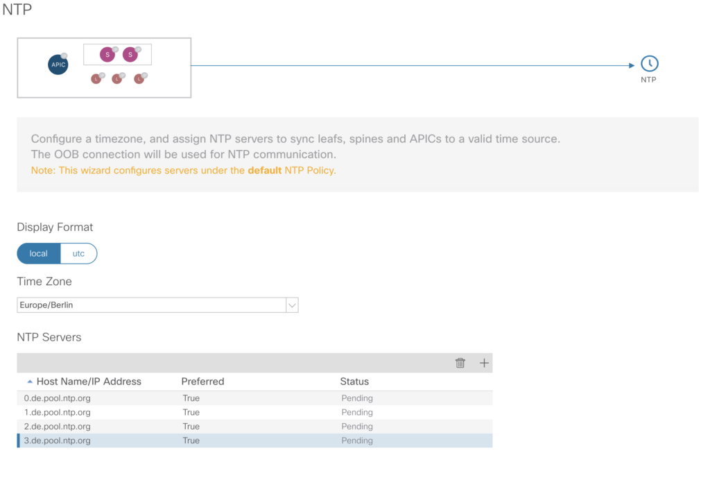
If you want to change it later – you’ll find the configuration via:
-> Fabric -> Fabric Policies -> Policies -> Pod -> Date and Time -> Policy Default
And as a last step
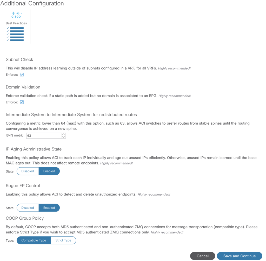
Additional configuration
based on Cisco best practices.
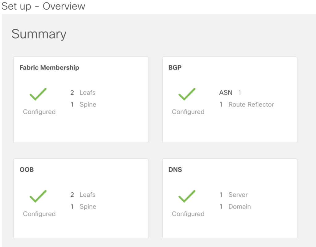
After this you’ll see in the overview:
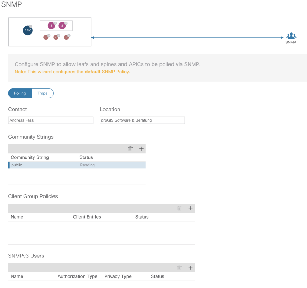
SNMP Configuration
We’ll just choose a very simple setup, with the well-known public community string, and do ignore those more strict v3 login features.